Sensors
Motion and magnetic switches.
The team designed their own board in Eagle that acts as the controller for the sensor. This board translates inputs from the sensors, converts them to trigger messages to sent to the app via MQTT. The board uses an ESP8266 E-12 chip as its microcontroller. The standard Arduino interface is used to program the board after manufacturing. The programmer uses a USB to UART converter to connect to the computer, while the board has header pins on its edge. Further details about the capabilities of the sensor boards will be described in the next section.
Hardware
The sensor boards utilize the ESP8266 microcontroller, which has an antenna and built-in Wi-Fi capabilities. Our group has demoed this Wi-Fi connectivity with the SparkFun Dev Thing, listed in Section 7, a programmable microcontroller with a ESP8266 chip. The boards use a 3.7 volt Lithium-ion battery rated for 2000 mAh for power, with a wallwart for operating the board without the battery and charging a low battery. An LED on the board will indicate if the battery is charging. The board will run at 3.3 VDC (set by a voltage regulator). A power cable will be provided with the system.System Operation
Once installation is complete, each sensor should be set up at entry points or monitoring rooms so that any unwanted movement or action will be detected. For example, an entry sensor on a back window. If this window is opened or broken, the one-shot chip on the board will register a state change, and send a reset pulse to the ESP to wake it from sleep. Once awake, the ESP will check the state of a pin monitoring the sensor. If the sensor is triggered, in this example an open circuit, then it will write a ‘triggered’ value to memory and attempt to connect to WiFi. This memory writing is done so that if the chip is reset while attempting to connect to WiFi, for instance if the entry sensor was on a door and it was closed seconds later, a ‘triggered’ message will still be sent when the ESP is able to connect.
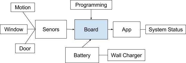
After connecting to WiFi, the ESP publishes the ‘triggered’ message to a specific MQTT topic designated to that sensor. The user names the topic when setting up the system, and is used to differentiate between sensors. Once the message is sent, the board will clear the triggered state from memory and return to sleep. One can easily monitor if ‘triggered’ messages have been sent from any of the sensors using the mobile application. If, as in this scenario with a broken window, the sensor remains open after sending the initial ‘triggered’ message, it will wake up from sleep every 30 seconds and send another ‘triggered’ message. This sleep is used to conserve battery power to allow longer periods of use without charging. When the battery is low, a wall-charger can be plugged into the charging port, and a red LED indicates that the battery is charging. When the LED is turned off, the battery is fully charged.
System Flow Diagram
